The ceramic plunger slides into the sleeve, but catches halfway through. Or it moves freely, yet the pump delivers less liquid than expected.
In either case, the fit deserves a closer look. A plunger and sleeve can each pass their diameter inspection and still perform poorly together. Clearance, bore shape, surface finish and operating conditions all affect the assembled pair.
Too little clearance leaves limited room for movement. Contamination, misalignment or a temperature change may cause the plunger to stick. Resistance at one point along the stroke can indicate taper or variation in the bore.
Too much clearance creates a different problem. In pumps that rely on a close plunger-to-sleeve fit for sealing, liquid can pass through the gap. This internal leakage may reduce delivery volume and affect dosing consistency.
| What You Notice | What to Investigate |
|---|---|
| The plunger catches at one position | Bore taper, roundness, contamination or alignment |
| Movement becomes harder after installation | Mounting distortion and assembly alignment |
| Movement changes as the equipment warms up | Material expansion and operating temperature |
| Delivery falls under pressure | Clearance, wear, fluid viscosity, valves and seals |
These checks help narrow down the cause before changing the dimensions.
The same clearance will not suit every application.
In metering equipment, repeatability matters. Evaluate the pair at the intended pressure, speed and fluid viscosity, particularly when dispensing small volumes.
For chemical dosing, consider what happens to the liquid during operation and shutdown. Suspended particles, deposits or crystallisation can interfere with a close-running fit. Check material compatibility against the actual chemical and concentration.
In filling equipment, product temperature and viscosity may change between batches. Cleaning conditions matter too. A pair that moves smoothly with water at room temperature still needs evaluation with the intended product and operating cycle.
Start with the fluid, pressure, temperature and ceramic materials. Include the housing and mounting arrangement, because installation can affect the sleeve bore.
Different ceramic materials expand at different rates as temperature changes, so consider the material combination alongside the dimensions when specifying clearance.
Calculate clearance from the size limits of both parts.
For example, a sleeve bore of 10.004–10.006 mm and a plunger diameter of 10.000–10.002 mm produce a diametral clearance of 0.002–0.006 mm.
These figures illustrate the calculation only. The appropriate clearance needs engineering review for the actual application. For a centred plunger, radial clearance is half the diametral clearance.
Our guide to ceramic bushing fits explains the same calculation using bore and shaft limits.
Give the supplier clear diameter limits and the required clearance range. Where performance depends on them, specify roundness, cylindricity, surface finish and working length.
State whether the parts will be supplied as individually matched pairs or need to be interchangeable. This affects how they are manufactured, inspected and replaced.
It is tempting to put ±0.001 mm on every dimension. Before doing that, identify which dimensions actually control the fit. A mounting feature may have different requirements from the sliding surface. We discuss this in how tight is tight enough.
Ask how the bore is measured during finishing, how the finished parts are paired and what inspection records are available.
At CERAMPRO, technicians use air-gauge readings to monitor the sleeve bore during honing. We measure the plunger outside diameter and sleeve bore, check roundness where required, and pair suitable components according to their measured dimensions. Our article on precision honing and matching shows more of this process.
For critical dimensions, agree on 100% inspection and a suitable measurement method before production. Matched pairs should carry identification so they stay together during packing and assembly.
A slow, smooth descent check provides another observation of the fit. Keep the test conditions consistent, including cleanliness, orientation and the presence of liquid. Check leakage and dosing performance under the agreed operating conditions.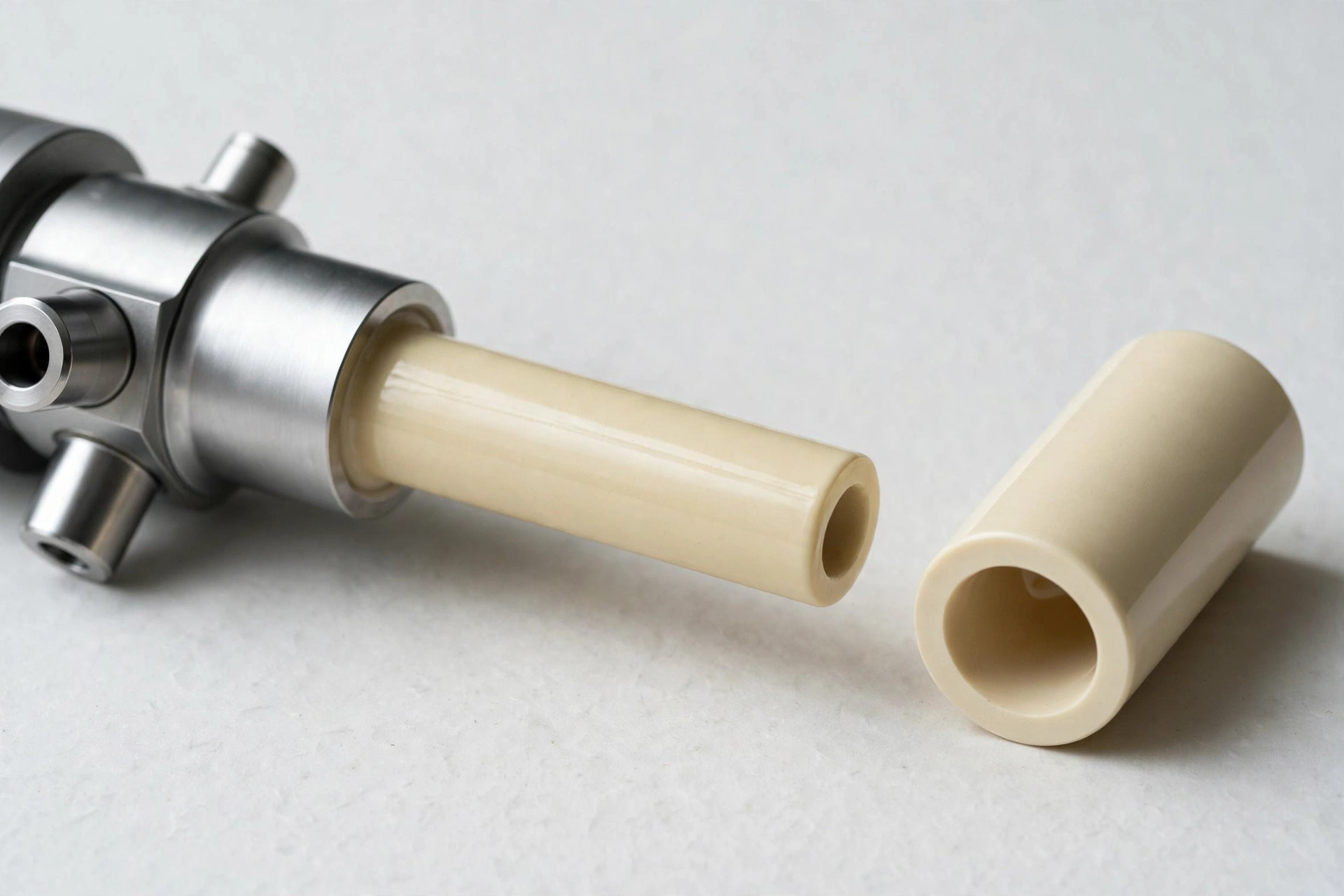
Reducing clearance can help control internal leakage, but the pair still needs enough running clearance for its operating conditions. Temperature, alignment, fluid properties and contamination all influence that decision.
A diameter reading does not describe the entire surface. Taper, roundness variation or mounting distortion may create a local tight spot. Check several positions along the working length and review the installed assembly.
Yes, subject to checking the sleeve’s actual dimensions and condition. Send its inspection results or a sample for evaluation. If the original assembly was selectively matched, the replacement also needs matching.
Send CERAMPRO your drawing, quantity and operating details, including the fluid, temperature and pressure. If you have a target clearance, leakage limit or dosing requirement, include it with the inquiry.
These details help our engineers review the material, machining process and inspection requirements, and prepare a quotation for your application.